


Picture a large triangle with one vertex inside the viewport and the other two well outside it. The GPU has to draw the visible part. What actually happens to the overhang?
That’s triangle clipping — and it isn’t a convenience feature. It’s a correctness requirement baked into every real-time graphics pipeline. The rasterizer can’t process geometry that falls outside a defined coordinate range. Skip clipping, and you don’t get a slower frame; you get a broken one.
This article covers what clipping is, why it’s mandatory, how it operates in clip space, and why the near plane is where the vast majority of real-world boundary bugs originate.
What Triangle Clipping Actually Is
Triangle clipping cuts each primitive to the portion that lies within the view volume. The result is a new set of smaller triangles — not the original triangle with parts masked off. The geometry is genuinely rebuilt at the boundary.
This is also where clipping and culling part ways:
- Clipping handles partial visibility. The primitive straddles the boundary. The GPU cuts it at the plane and keeps the inside portion.
- Culling handles full rejection. The primitive is entirely outside — or back-facing — and is discarded without further processing.
Culling is a filter: keep or throw away whole. Clipping is a reconstruction: trim and rebuild. Both are necessary, and neither substitutes for the other.
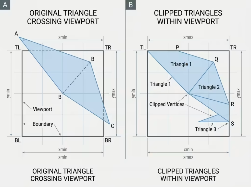
[Diagram: a large triangle crossing the viewport boundary alongside the smaller triangles that remain after clipping.]
Why Triangle Clipping Is Required
Clipping isn’t optional housekeeping. Omit it, and the pipeline produces wrong output or hits undefined behavior. Three separate guarantees depend on it.
Correctness at the screen boundary
The rasterizer iterates over primitives within a defined coordinate range. Geometry that overhangs the viewport falls outside what the fixed-function hardware can legally process.
The tempting shortcut — “just skip pixels outside the viewport” — doesn’t hold. The rasterizer may miss boundary pixels, misattribute edge coverage, or behave unpredictably when encountering out-of-range coordinates. Clipping removes the overhang before the primitive ever reaches that hardware. No overhang, no problem.
Valid perspective interpolation
Vertex attributes — depth, UVs, color, normals — are interpolated across the triangle with perspective correction. That math depends on the w component staying within a sensible range.
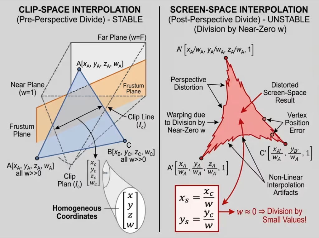
Near the near plane, w approaches zero, and the interpolation breaks down. Clip space is the domain where those guarantees still hold, because clipping occurs there before any division by w takes place. Every primitive that reaches the interpolation stage has already been trimmed to a range where the math works.
The pipeline contract
Each stage trusts the one before it. The vertex shader outputs clip coordinates. The perspective divide and the rasterizer both assume those coordinates fall within the expected clip-space range.
Clipping enforces that assumption. Without it, downstream stages operate on data they were never designed to handle. Clipping converts “anything the vertex shader might output” into “geometry the rasterizer can process correctly.”
Where Clipping Fits in the GPU Pipeline
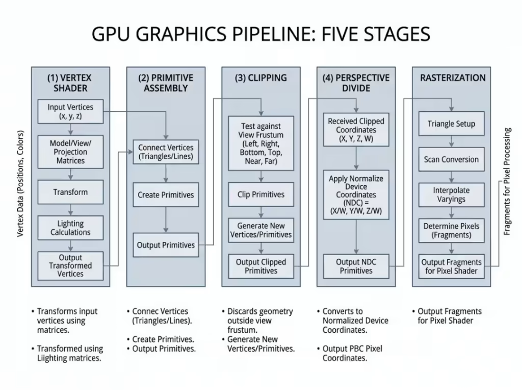
The stage order is fixed:
Vertex Shader → Primitive Assembly → Clipping → Perspective Divide → Rasterization
[Diagram: linear pipeline showing these five stages in order.]
The reason clipping must occur before the perspective divide is the key insight. The divide maps from clip space to normalized device coordinates by dividing x, y, and z by w. Do that first, and vertices near or behind the camera — where w is tiny, zero, or negative — collapse into meaningless coordinates. The geometric data needed to place the cut correctly is gone before clipping can use it.
Clipping in clip space keeps w intact. Those values are precisely what the GPU needs to compute accurate intersection points and interpolate attributes at new vertices. The ordering isn’t a convention; it’s a hard constraint imposed by the math.
How GPU Triangle Clipping Works
There’s more to clipping than a simple cut.
Clipping operates in clip space, not screen space
The vertex shader produces four-component clip coordinates — (x, y, z, w). Clipping tests these against the clip planes before any division by w occurs.
In clip space with w intact, inside/outside comparisons against each clip plane are numerically stable. Attempt those same tests after the perspective divide — in NDC or screen space — and they become unreliable near the near plane, where w approaches zero and divided coordinates have already become extreme. Clip space is the only domain where GPU triangle clipping is geometrically safe for near-camera geometry.
Edge-by-edge plane testing
Clipping works plane by plane. For each clip plane, every vertex is classified as inside or outside.
When an edge connects an inside vertex to an outside vertex, it crosses the plane. The GPU computes the exact intersection point, then reconstructs the surviving primitive from the retained vertices and the newly computed intersection vertices. This is the structure of the Sutherland–Hodgman algorithm: process the polygon against each plane in sequence, passing the result to the next.
Re-triangulating the clipped polygon
Clipping a triangle against a single plane can produce a quadrilateral. Clipping against multiple planes can leave a polygon with five or more vertices.
The rasterizer only accepts triangles. The clipped polygon must be broken back into triangles — typically via a triangle fan — before it moves downstream. One input triangle can become two, three, or more output triangles, each fully inside the view volume.
Attribute interpolation at new vertices
Every vertex produced at a clip boundary needs a full attribute set: UVs, vertex color, normals, depth. These are linearly interpolated along the clipped edge, weighted by the fraction of the intersection that falls between the two original endpoints.
This is where subtle bugs hide. If the interpolation is wrong or missing, geometry looks correct while shading, texturing, or depth values break along clip boundaries — a discontinuity visible only at the edges where clipping occurred. The geometry can be clean while the attributes are quietly wrong.
Why the Near Plane Causes So Many Problems
The near plane is where clipping earns its keep. Almost every severe boundary artifact — geometry flipping, projection smearing, coordinate explosion — traces back here, not to the far plane or screen edges.
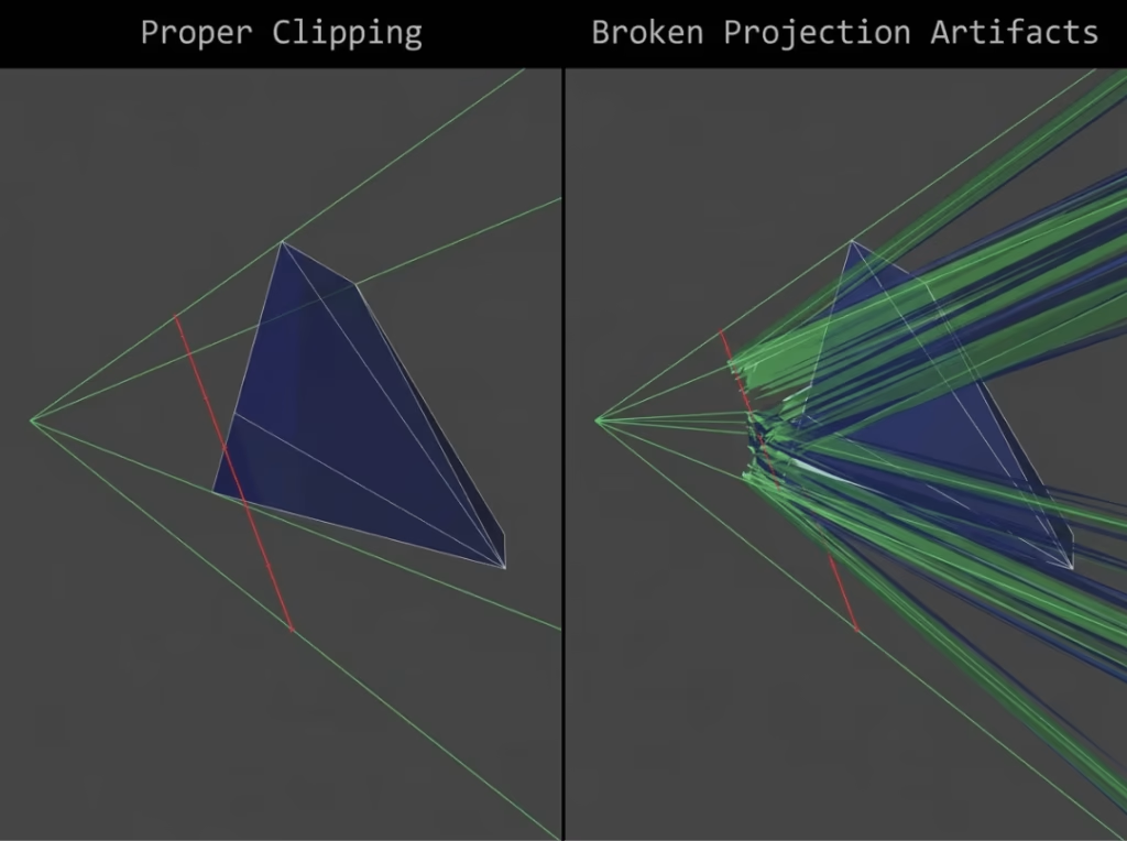
Behind-camera vertices can’t be projected
Vertices behind the camera produce a negative or zero w. There’s no valid screen position for a point behind the viewer, and the projection math doesn’t yield a sensible answer.
Without near-plane clipping, those vertices reach the perspective divide. The results are immediate and dramatic: geometry flips, stretches across the entire screen, or smears in ways that bear no relationship to the actual scene. Near-plane clipping intercepts that geometry before it reaches the divide, so it never gets the chance to corrupt the frame.
Near-zero w causes numerical amplification
The perspective divide amplifies floating-point imprecision in proportion to 1/w. When w is large, rounding errors stay small. As w approaches zero, the same error translates into an increasingly large screen-space displacement.
At w = 1.0, an error of 0.001 is negligible. At w = 0.001, dividing by it turns that same error into a displacement of 1.0 in NDC — potentially hundreds of pixels on screen. Near-plane clipping removes geometry with near-zero w before it reaches the divide, preventing that amplification entirely.
Near-plane crossings are far more common than far-plane crossings
The far plane sits at a large positive depth where w is well-behaved. Problems there tend to be gradual — z-fighting, depth banding — not sudden geometry explosions.
The near plane sits exactly where w collapses. And unlike the far plane, it’s crossed constantly in normal camera operation: walking through geometry, zooming in on a surface, an object coming too close to the camera. Far-plane crossings require the camera to look at geometry far in the distance. Near-plane crossings happen dozens of times per frame in a typical scene.
Practical steps for near-plane problems
You can’t bypass clipping, but you can avoid feeding the pipeline geometry that stresses it:
- Set the near plane as large as your scene allows. Pushing it too close to zero degrades depth-buffer precision across the scene and increases the frequency with which triangles cross it. Most scenes tolerate a near value of 0.1 or higher without visible issues.
- Break up large triangles. A single triangle spanning a large chunk of world space is far more likely to cross the near plane than smaller, well-distributed geometry. Subdivision reduces both the frequency and severity of crossings.
- Debug near-plane issues by checking w first. When the boundary geometry looks wrong, inspect the clip-space w-values of the suspect vertices. A negative w means the vertex is behind the camera. Then verify the near-plane value in the projection matrix. Those two checks resolve most near-plane artifacts in practice.
Guard-Band Clipping
Guard-band clipping is a hardware optimization layered on top of standard clipping. The GPU maintains an extended region around the viewport — the guard band — that is larger than the visible screen area.
Triangles that poke slightly past the viewport edge but stay within the guard band skip full geometric clipping. They pass to the rasterizer intact, which handles the visible boundary via scissor logic. This avoids generating new vertices for the common case of a triangle with a small screen-edge overhang.
The critical point: guard-band clipping does not bypass correctness requirements. Any triangle that crosses the near plane still requires full geometric clipping. Any triangle extending beyond the guard band itself requires it too. The guard band reduces costs for the easy case — minor screen-edge overhangs — but not for cases where correctness is at stake.
When large or camera-crossing primitives cost noticeably more to process than neighboring geometry, it’s usually because they hit the guard-band threshold.
Common Clipping Problems in Practice
Edge artifacts from incorrect attribute interpolation
Shading discontinuities or texture seams along viewport edges almost always indicate incorrect attribute interpolation at clip-generated vertices. If the geometry is correct but shading or texturing breaks at the boundary, the attribute math at newly created vertices is the first place to look.
Sliver triangles
When a primitive barely grazes a clip plane, the output can be an extremely thin or zero-area triangle. These degenerate primitives cause rasterization instability and unpredictable overdraw. Scenes with high primitive density near frustum boundaries — dense foliage, particle systems, fine terrain — should account for the sliver triangles clipping will produce.
Large world coordinates
Very large positional values reduce floating-point precision in clip-space calculations, making intersection points less accurate and worsening downstream depth artifacts. Camera-relative rendering — transforming scene geometry so the camera sits near the origin — is the standard solution for keeping clip-space arithmetic numerically stable at large scales.
Frustum culling is not a replacement
Frustum culling removes draw calls or objects that fall entirely outside the view volume. It doesn’t handle primitives that straddle the boundary. Rely on culling alone, and every partially visible triangle at the frustum edge goes unclipped and renders incorrectly. Both mechanisms are necessary; they operate at different levels of granularity.
How to Think About Clipping as a Developer
A few principles that hold across every rendering context:
- Clipping is a correctness step, not an optimization. It can’t be safely disabled, and there’s no shortcut to skip it without producing incorrect output.
- The near plane is the highest-risk boundary. It’s where numerical instability concentrates and where the artifacts you’ll actually have to chase originate.
- Oversized and camera-crossing triangles drive the most expensive, artifact-prone clipping. Well-distributed geometry limits both the cost and the side effects.
When a boundary artifact appears, this sequence resolves most cases:
- Inspect clip-space positions. Are any vertices outside the expected range?
- Check the sign of w. Negative w means the vertex is behind the camera.
- Verify the near-plane value in the projection matrix. Is it tighter than the scene actually requires?
- Look for abnormally large primitives spanning a significant portion of the view volume.
Those four checks cover the majority of boundary rendering bugs.
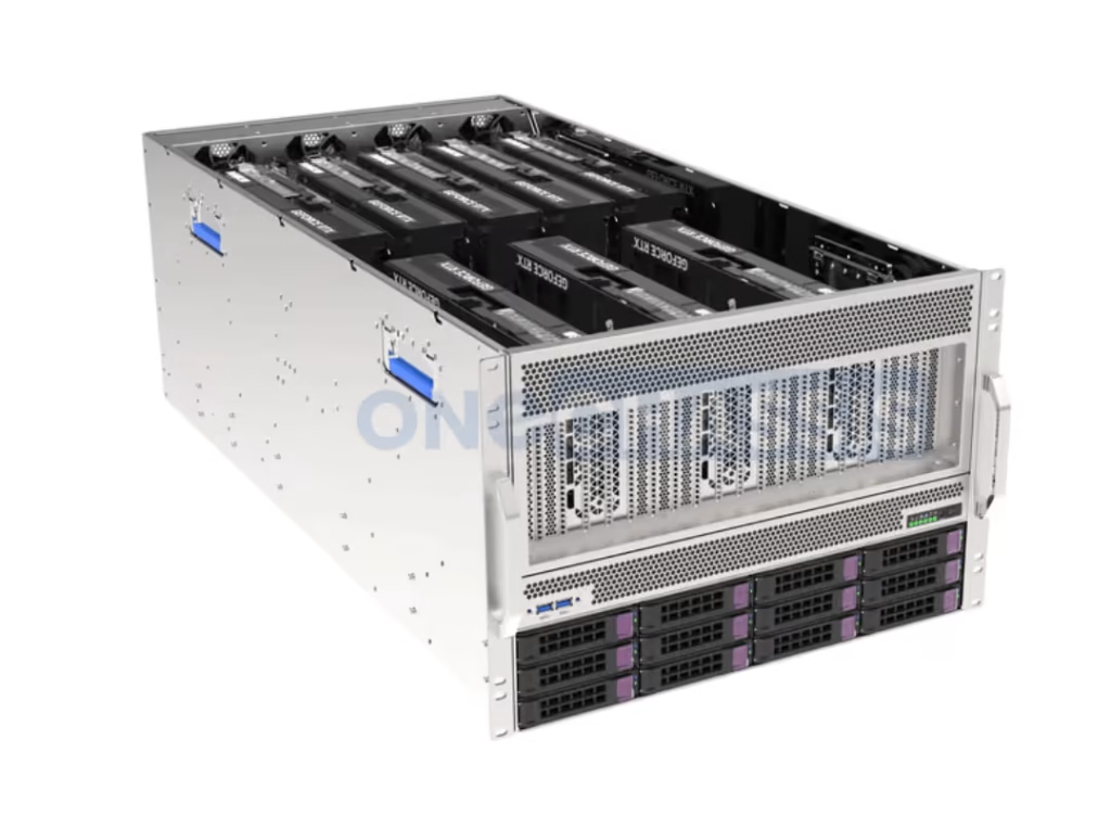
If you’re building or selecting the physical hardware that runs these pipelines — particularly multi-GPU rendering rigs or inference servers — the chassis design matters as much as the pipeline configuration. GPU server cases built for sustained parallel workloads must handle the thermal and power demands of cards during long rendering or compute sessions, and the physical layout directly affects how stable those workloads are under load.
Frequently Asked Questions
Is triangle clipping the same as frustum culling?
No. Frustum culling discards primitives that are entirely outside the view volume. Triangle clipping handles primitives that partially overlap the boundary — cutting them at the plane and keeping the inside portion. Both are part of the pipeline, and neither substitutes for the other.
Why does clipping happen before the perspective divide?
Dividing by w first destroys the data needed to clip correctly near the near plane. When w is very small or negative, the perspective divide produces extreme or undefined coordinates. Clipping in clip space, before that division, preserves w so intersection points can be computed accurately.
What happens to UVs and other attributes after clipping?
Every new vertex created at a clip boundary receives attribute values interpolated along the clipped edge, proportional to the fraction of the distance along the edge from the original endpoints where the intersection falls. UVs, vertex color, normals, and depth are all handled this way. Errors here produce shading and texture discontinuities that appear only along clip boundaries.
Can the GPU skip clipping for triangles fully inside the view volume?
Yes. Primitives entirely inside the view volume pass a trivial-accept test and bypass geometric clipping. Guard-band clipping extends this: triangles that extend slightly past the viewport but stay within the guard-band region are also passed through, with edge trimming handled by the rasterizer’s scissor logic.
Does triangle clipping add noticeable performance cost?
Usually not. Most primitives pass trivial-accept or are culled, and guard-band logic handles small overhangs cheaply. Cost rises when many primitives straddle clip planes simultaneously — the main practical reason to avoid submitting unnecessarily large triangles to the pipeline.
Why does the near plane cause more visible problems than the far plane?
The far plane sits at a depth where w is large and numerically stable; artifacts there tend to be gradual— z-fighting and depth banding. The near plane occurs when w approaches zero, so any geometry that crosses it produces an immediate correctness failure rather than a gradual precision issue. And unlike the far plane, the near plane is constantly crossed during typical camera operation.
The Mental Model
The vertex shader defines the triangle’s position in clip space. Clipping constrains it to the range downstream stages can safely process. The rasterizer fills only what legitimately remains.
Nearly all of the practical weight of this stage concentrates at the near plane — where w collapses, projection math breaks down, and the artifacts that show up in real scenes originate. Setting the near-plane value correctly, avoiding large camera-crossing primitives, and recognizing that attribute interpolation is part of the clipping operation: these habits prevent most boundary rendering bugs before they start.
Clipping isn’t a background detail the GPU quietly handles for you. Understanding it changes how you reason about camera setup, floating-point precision, and every visual artifact that appears at the limits of what the camera can see.
