

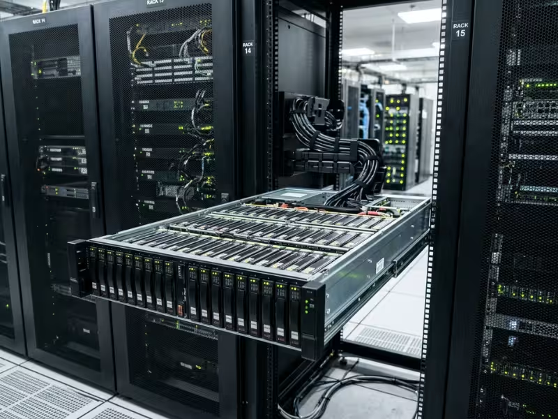
A top-loading storage server is a high-density rack chassis, usually 4U tall, where hard drives install vertically from the top rather than through the front panel. A typical design holds 60 to 90 or more 3.5-inch drives in a single enclosure — built to put as much raw capacity as possible into as little rack space as possible.
That density isn’t free. Top-loading systems are heavy, require deep racks, and are serviced with the chassis pulled forward on its rails while still running. Teams that plan for these constraints get a strong capacity platform. Teams that don’t end up with hardware that won’t fit the cabinet, can’t be safely serviced, or risks tipping the rack.
In this guide, you’ll learn:
- How the top-loading design works and why it changes the density math
- What’s inside the chassis and why each part matters
- Where top-loading fits, and where front-loading is still the better choice
- How to choose a top-loading chassis for your deployment
What Is a Top-Loading Storage Server?
Picture a 4U chassis with no drive bays on the front panel. The drives stand upright in rows running across nearly the full depth of the enclosure — like files in a drawer. To reach them, you slide the whole chassis forward on its rails and open a cover on top. Cooling still runs front to back, pulled across the drive rows by a fan wall.
This is a capacity design, not a performance design. It’s built for bulk storage measured in hundreds of terabytes or petabytes, where cost per terabyte and rack footprint matter more than IOPS or latency. If your workload lives on NVMe and depends on fast random reads, this isn’t the right tool.
Top-Loading vs Front-Loading: The Core Design Difference
The difference comes down to which surface of the chassis holds the drives.
A front-loading chassis is bounded by its front panel. A 4U front panel fits around 24 drives; add rear bays and you reach roughly 36. Beyond that, there’s simply no more panel area.
A top-loading chassis uses the floor of the enclosure instead. Floor area grows with depth, so depth becomes capacity. A chassis 800 mm or more deep can hold many rows of drives stacked behind one another. That one change explains the density advantage — and every trade-off that follows: weight, rack depth, cooling across many rows, and service from above.
Storage Server or JBOD? Two Ways to Use the Same Chassis
The same top-loading enclosure typically ships in two configurations, and buyers often confuse them.
A top-loading storage server includes its own motherboard, CPUs, memory, and network interfaces. Each unit is a self-contained node that runs storage software locally. A top-loading JBOD (“just a bunch of disks”) holds only drives, SAS expanders, and power — no compute. It connects to a separate head node over external SAS cables.
Choose the server version when your storage software runs on each node, as most scale-out object and distributed file systems do. Choose JBOD when you have capable head nodes and need more capacity behind them without adding CPUs, memory, or software licenses.
Inside a Top-Loading Chassis: Key Components
Every major component in a top-loading chassis answers one of four constraints: density, weight, heat, or service access. Understanding each part makes spec sheets easier to evaluate.
- Drive bays and tool-less carriers: Drives sit vertically in slots across the chassis floor. Tool-less latches matter more here than in front-loading designs, since swaps happen with the chassis extended and a technician working from above.
- Backplanes: Distribute power and signal to the drive rows. In top-loading designs, backplanes are usually split into sections across the floor — check whether a single backplane failure affects one row or many.
- SAS expanders: Let a small number of host ports reach dozens of drives. Better designs use dual expanders for redundant paths, so losing one expander doesn’t take every drive offline.
- Fan wall: A row of fans pulls air from the front across densely packed drives to the rear. Drives at the back receive pre-warmed air, so fan capacity and ducting determine whether rear rows stay within temperature limits. Hot-swap fans are standard on well-engineered designs.
- Redundant PSUs: Many drives spinning up together draw a large current spike. Redundant 1+1 or N+1 supplies, combined with staggered spin-up, keep startup and failover stable.
- Heavy-duty slide rails and cable management arm (CMA): Rails carry a fully loaded chassis at full extension. The CMA folds and unfolds to keep power and data cables connected while the system slides out for service.
- Compute module (server version): The motherboard, CPUs, memory, and NICs — typically positioned at the rear of the chassis behind the drive area.
- Reinforced chassis structure: A rigid frame prevents flex under heavy load and limits rotational vibration between drives, which can quietly erode HDD throughput when dozens of spindles share one enclosure.
How a Top-Loading Storage Server Works: From Rack to Drive Swap
A front-loading server is serviced at the front panel — pull a drive, push in a replacement. A top-loading server is serviced from above, turning what looks like a simple swap into a short but deliberate procedure.
- Identify the drive. Management software flags the failed drive, and bay LEDs mark its location. Confirm the exact position before opening anything. With dozens of identical drives in neat rows, pulling the wrong one during a rebuild is a real risk.
- Extend the chassis. Slide the running chassis forward on its rails. The CMA keeps power and data connected. Before extending a heavy unit, confirm the rack is anchored or has anti-tip support — especially if the chassis sits high in the cabinet.
- Open the top cover. A sliding or hinged cover exposes the drive area. With the cover open, the fan wall no longer forces air through the drive rows, so temperatures begin to rise. Many vendors specify a maximum open-cover time. Know that number before you start.
- Swap the drive. Release the tool-less carrier, lift the failed drive straight up, and insert the replacement. The storage software or RAID controller detects the new drive and begins rebuilding.
- Close and retract. Close the cover to restore airflow, slide the chassis back into the rack, and confirm the rebuild has started and all fans report normal status.
Each step depends directly on chassis design. Rail strength determines whether extension is safe. CMA length determines whether cables stay connected. Cover design affects how quickly you can open and close. Thermal headroom sets how long you can work. These four factors come back in the selection checklist — they’re what separates a chassis that’s easy to operate from one that only reads well on paper.
Why Top-Loading Matters for High-Density Storage
The design delivers two measurable gains: more capacity per rack unit and lower cost per terabyte. It also brings hard constraints that must be planned for before you commit rack space.
More Capacity per Rack Unit
A typical front-loading 4U server chassis holds 24 to 36 drives. A typical top-loading 4U chassis holds 60 to 90 or more.
Scale that to a full rack. Put eight 4U chassis in a 42U cabinet and you still have roughly 10U left for top-of-rack switches, PDUs, and cable management. With front-loading 24-bay units, eight chassis give you 192 drives. With top-loading units, the same eight chassis give you roughly 480 to 720 drives. At 20 TB per drive, that’s about 3.8 PB raw versus 9.6 to 14 PB raw in the same footprint. These are typical figures — verify against your actual chassis and drive choices.
The practical result: fewer racks, less floor space, fewer PDUs, and fewer cable runs for the same capacity target.
Lower Cost per Terabyte and Simpler Cabling
The cost advantage comes from node count, not from the drives themselves. Drives cost the same in either chassis. What changes is how much supporting hardware surrounds them.
More drives per node means fewer nodes for the same capacity — and fewer nodes means fewer motherboards, CPUs, memory kits, NICs, switch ports, optics, and cables per terabyte. It can also mean fewer per-node software licenses. In JBOD mode, a single head node can control several enclosures, so you add capacity without adding compute at all.
The exact savings depend on your platform, pricing, and software model. The direction is consistent: as capacity grows, top-loading reduces the overhead hardware that scales with it.
The Trade-Offs You Must Plan For
Every density gain shows up somewhere else. These are the constraints that cause problems when nobody plans for them:
- Weight: A fully loaded 60-bay unit commonly falls in the 70–100 kg range; larger designs weigh more. Verify per model. You’ll need a four-post rack, rails rated for the load, a cabinet rated for the total weight, and usually two people or a server lift for installation.
- Depth: Chassis depths of 800 mm or more are common. Plan for deep cabinets, often 1000–1200 mm, with room left for the CMA and rear cabling.
- Service clearance: The chassis must extend fully in front of the rack. Narrow aisles or blocked cabinet fronts make service unsafe or impossible.
- Vibration: Dozens of spinning drives in one rigid enclosure generate rotational vibration. Without a stiff chassis and well-designed carriers, sustained throughput can degrade silently.
- Rack stability: Extending a 90 kg chassis near the top of an unanchored rack shifts the center of gravity forward. Install heavy units low, and anchor the cabinet.
Where Top-Loading Storage Fits Best
Top-loading pays off when capacity matters more than IOPS and data volume grows steadily. Each workload below follows the same format: what it is, why top-loading fits, and what to watch.
Scale-Out Object and Cloud Storage
Workload: Object storage clusters that spread data across many nodes using erasure coding or replication.
Why top-loading fits: High drive counts per node reduce the total node count for a given capacity, cutting network ports, power draw, and management overhead.
What to watch: Failure domain size. One chassis can hold a large share of cluster data. Erasure coding profiles and placement policies must ensure that losing — or taking offline — a full node doesn’t threaten data availability.
Backup, Archive, and Cold Data
Workload: Backup targets, compliance archives, and write-once, read-rarely data.
Why top-loading fits: High-capacity HDDs are the right drive for this workload, and top-loading JBODs extend backup targets without adding compute.
What to watch: Rebuild time. With very large drives, a single rebuild can take days under production load. Use protection schemes that tolerate a second failure during that window.
Video Surveillance Retention
Workload: Monitoring centers for cities, transit systems, campuses, and industrial sites, writing continuous camera streams for long retention periods.
Why top-loading fits: Delivers large retention capacity in fewer racks — important in control rooms where space and power are constrained.
What to watch: Sustained write performance under constant load. Use drives rated for 24/7 surveillance or enterprise duty, and size controllers and network links for total camera bitrate, not just capacity.
AI and Analytics Data Lakes
Workload: Raw training datasets, sensor logs, and historical data sitting behind a faster NVMe tier.
Why top-loading fits: HDD-based top-loading nodes provide the low-cost capacity tier that GPU compute clusters read from.
What to watch: Network bandwidth per node. Ninety drives behind one node can deliver more aggregate throughput than a single 25 GbE link carries. Match NIC speed and count to drive count, or the network becomes the bottleneck.
Top-Loading vs Front-Loading Storage Chassis
Both designs use the same drives. The real choice depends on which constraint limits you more: rack space or service simplicity.
|
Factor |
Top-Loading |
Front-Loading |
|---|---|---|
|
Drives per 4U (typical) |
60–90+; highest density available in 4U |
24–36; limited by panel area |
|
Capacity per rack |
Very high; fewer racks for the same capacity |
Moderate; needs more racks at petabyte scale |
|
Service method |
Extend chassis, open cover; slower, needs clearance |
Swap from front panel; fast and straightforward |
|
Chassis weight |
Very heavy loaded; needs rated rails and lifting help |
Lighter; easier to install and relocate |
|
Rack depth needed |
Deep cabinets, often 1000 mm+; may not fit existing racks |
Standard depths; fits most cabinets |
|
Failure domain |
Large; one node holds a lot of data |
Smaller; easier to absorb losses |
|
Best fit |
Capacity storage, archive, surveillance, data lakes |
Performance storage, smaller sites, mixed workloads |
Choose top-loading when you’re building capacity measured in petabytes, when rack space or power is tight, or when cost per terabyte drives the decision. Choose front-loading for performance-sensitive storage, smaller deployments, or sites where extending a heavy chassis isn’t practical or safe.
How to Choose a Top-Loading Storage Chassis
Start with your capacity target and your physical site. The chassis follows from those two inputs — not from the highest bay count in a catalog.
Selection Checklist
- Capacity and bay count. Calculate usable capacity after RAID or erasure coding overhead, then add planned growth. Choose a bay count that meets the target without creating an oversized failure domain.
- Server or JBOD. Does each enclosure need its own compute, or will it attach to existing head nodes? This affects cost, power draw, and software licensing.
- Drive interface and backplane. Confirm SATA, SAS, or mixed support. For high availability, check for dual expander paths — and remember that dual-path access requires SAS drives.
- Rack depth and weight rating. Measure usable cabinet depth after the CMA and rear cables. Confirm four-post support and the rated load per rail pair and per cabinet.
- Rails and CMA. Require full extension, a load rating above your fully loaded chassis weight, and a CMA long enough for your actual cable bundle.
- Power and cooling. Check PSU redundancy, staggered spin-up support, fan redundancy, and the vendor’s open-cover time limit. Ask specifically how rear drive rows are kept within temperature limits.
- Structure and vibration control. Evaluate frame rigidity, carrier design, and drive retention. These determine long-term throughput and drive life more than any headline spec.
Common Planning Mistakes
- Ordering for capacity without checking cabinet depth. The chassis arrives, and it doesn’t fit the existing racks.
- Installing heavy units high in an unanchored rack. The first service extension becomes a tipping hazard.
- Using a CMA that’s too short for the cable bundle. Cables pull loose during extension, turning routine service into an unplanned outage.
- Ignoring network bandwidth per node. Dozens of drives sit behind a link that can’t keep up, and rebuilds crawl.
- Placing too much data in one chassis for the protection scheme. Losing a single node then risks data availability across the cluster.
Building a Top-Loading Storage Platform with Onechassis
Onechassis designs and manufactures server and storage chassis for system integrators and OEMs building capacity storage platforms. Our focus is the enclosure engineering that sits behind the trade-offs discussed above: structure, airflow, and integration.
- Structural design: Reinforced frames and rail systems built for heavy, high-density loads and safe extension during service.
- Thermal engineering: Fan wall layouts and ducting designed to keep rear drive rows within temperature limits in dense configurations.
- Compatibility: Integration support for backplanes, SAS expanders, and server motherboards, so the platform validates once and builds consistently at volume.
- OEM/ODM customization: Front panels, branding, layout changes, and volume production through our OEM service.
Send us your capacity target, rack dimensions, and deployment model. Our engineering team will recommend a standard chassis or work with you on a custom design.
FAQs About Top-Loading Storage Servers
How many drives does a top-loading storage server hold?
A typical top-loading 4U chassis holds 60 to 90 or more 3.5-inch drives, depending on depth and layout. Usable capacity depends on drive size and your RAID or erasure coding overhead — plan from usable terabytes, not raw bay count.
Can you replace drives while a top-loading server is running?
Yes, if the chassis has hot-swap backplanes, rated slide rails, and a cable management arm. You extend the running system, open the cover, and swap the drive. Keep the cover open only as long as necessary, and follow the vendor’s open-cover time limit.
What rack depth do top-loading storage servers need?
Most require deep cabinets — often 1000 to 1200 mm — because chassis depths of 800 mm or more are common. You also need clear aisle space in front of the rack to extend the chassis fully. Always check the model’s spec sheet against your cabinet’s usable depth.
Is a top-loading chassis better than a front-loading one?
It depends on your priority. Top-loading wins on density and cost per terabyte. Front-loading is better for performance storage, smaller deployments, and straightforward service. Choose based on your main constraint: rack space and capacity favor top-loading; speed and ease of access favor front-loading.
What is the difference between a top-loading storage server and a traditional NAS?
A traditional NAS is a finished appliance — fixed hardware, built-in software, and limited expansion. A top-loading storage server is an infrastructure-grade platform designed for integrators and enterprises who need to control the drive count, software stack, networking, and protection scheme at scale. NAS suits smaller deployments where simplicity matters. A top-loading platform suits environments where capacity is measured in petabytes, uptime is non-negotiable, and the storage layer must integrate into a broader data center or cloud architecture.
How much does a fully loaded top-loading storage server weigh, and what rack infrastructure does it require?
A fully loaded top-loading storage server can weigh anywhere from 70 to over 100 kg depending on drive count, chassis size, and configuration — always verify the exact figure in the model’s spec sheet before ordering. That weight demands a four-post rack with rails rated to match, a cabinet with a sufficient total load rating, and a stable floor or raised floor system capable of supporting the full rack weight. For installation and future drive swaps, plan for two people or a server lift. The rack itself must be bolted to the floor or anchored with an anti-tip kit, particularly if heavy units sit above mid-rack height.
Can a top-loading storage server be used in an edge or remote site deployment?
Generally, no — and the reasons are physical rather than theoretical. Top-loading storage servers are heavy, deep, and require stable four-post racks with anchored cabinets, clear aisle space for chassis extension, and reliable power with redundancy. Most edge and remote sites can’t meet all of those conditions. If you’re deploying storage at an edge location with limited space, shallow racks, or restricted access for service personnel, a front-loading server chassis or a compact storage appliance is a more practical fit. Top-loading platforms belong in data centers, large monitoring centers, and controlled infrastructure environments where the rack depth, floor loading, and service clearance are designed in from the start.
Conclusion
Three factors determine whether a top-loading storage server is right for your deployment:
- Top-loading turns chassis depth into capacity — that’s why it can hold two to three times the drives of a front-loading 4U unit.
- That gain comes with weight, depth, and service constraints that need to be planned at the rack level, not discovered on installation day.
- Selection starts from your capacity target and your physical site, then works back to the chassis.
Before comparing models, write down your usable capacity target, cabinet dimensions, and deployment model. Then contact Onechassis for a chassis recommendation or a custom build that fits all three.
