
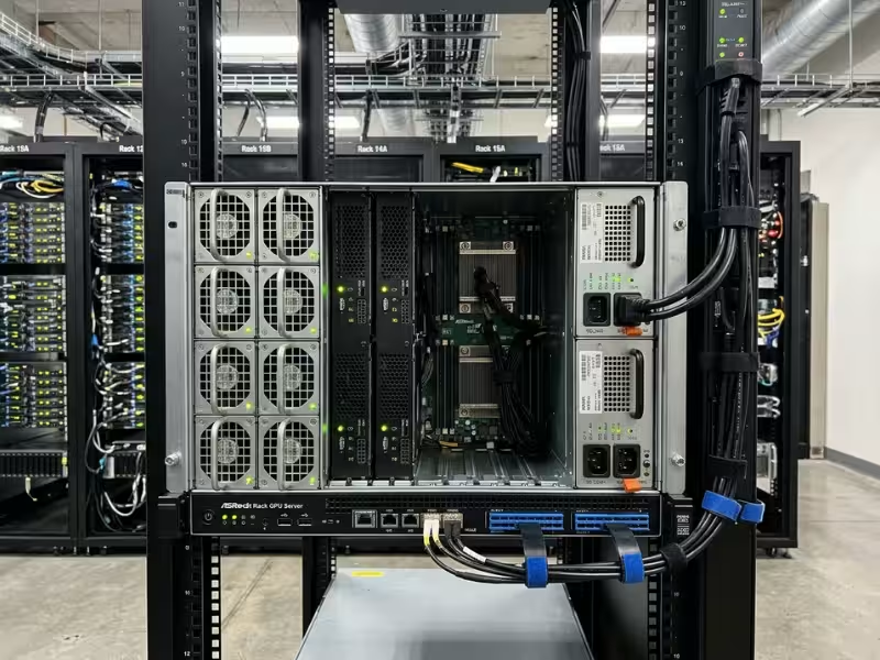
A GPU server chassis used to be something you picked after choosing the GPUs. That order no longer works. A single data center accelerator now draws 300–700 W. A fully loaded 8-GPU node can pull anywhere from about 4 kW to more than 10 kW. At those numbers, the chassis is no longer a metal enclosure—it is a thermal and power system that happens to be made of steel.
The wrong choice shows up quickly. GPUs throttle under sustained load. A card arrives and its power connector hits the lid. A PSU fails and the “redundant” supplies can’t carry the full load. Or a rack that looked fine on paper can’t deliver the kilowatts the nodes need.
Teams reach this decision from different starting points. An AI team may be scaling fine-tuning from one node to a full rack. A data center planner may need to fit GPU nodes into racks capped at 17 kW. A system integrator may be building edge inference boxes for a factory floor that hits 40 °C in summer.
This guide works through the decision in the order engineers actually face it: form factor, physical fit, cooling, power, PCIe topology, expansion, serviceability, deployment scenario, and total cost.
What a GPU Server Chassis Actually Determines
A GPU server chassis differs from a general-purpose server chassis in four key ways. It has wider slot spacing for double-width cards. It uses high-static-pressure fan walls to push air through dense heatsinks. It carries multi-kilowatt power supplies. And it often includes a PCIe switch backplane so more GPUs can connect than the CPUs alone could support. A standard 2U compute server has none of these, which is why moving GPUs into one rarely ends well.
Once you choose a chassis, it sets hard limits on five things:
- GPU density: how many cards fit, and at what width
- Thermal capacity: how many watts it can remove at a given inlet temperature
- Power headroom: how much load it can carry, including during a PSU failure
- Expansion: how many lanes, slots, and drive bays remain after the GPUs are installed
- Serviceability: how fast a technician can swap a failed part
The physical baseline is standard. GPU servers mount in 19-inch racks. Height is measured in rack units, where 1U equals 1.75 inches (44.45 mm). Depth varies more. Many GPU nodes run 700–900 mm deep, and some baseboard systems go deeper. Tower and workstation chassis have their place in labs, but they are outside the scope of this guide. Everything here assumes rack-mount deployment.
Rack Form Factors: From 1U/2U to 4U, 5U, and Beyond
Chassis height maps almost directly to two things: how many GPUs fit and how much air can move through them. More height means bigger fans, more ducting space, and more room between hot components.
The table below shows what each class realistically supports:
|
Form Factor |
Typical GPU Count |
Typical Per-GPU TDP |
Best-Fit Workloads |
Main Constraint |
|---|---|---|---|---|
|
1U |
1–4 (single- or double-width) |
70–350 W |
High-density inference, video analytics |
Limited thermal headroom, small fans running at high RPM |
|
2U |
2–4 double-width or up to 8 single-width |
70–400 W |
Inference, VDI, mixed compute |
Tight card clearances, fewer expansion slots |
|
4U |
8 double-width (some designs fit 10) |
300–600 W |
Fine-tuning, mid-scale training, large-model inference |
Per-node power of 3–6 kW |
|
5U |
8–10 double-width |
400–600 W |
Higher-TDP PCIe cards, storage-heavy AI nodes |
Rack space and weight |
|
6U–10U (baseboard) |
8 SXM/OAM modules |
700–1,000+ W |
Large-scale training |
Node power of 10 kW+, often needs liquid cooling |
4U GPU server cases dominate PCIe GPU deployments for practical reasons. About 177 mm of height lets full-height, full-length cards sit in risers at double-width spacing. That still leaves room for a dedicated fan wall and ducting. It also allows the CPU and memory to sit in a separate airflow zone, so GPU exhaust doesn’t preheat the processors. Technicians can usually reach every GPU through a top lid or a front-loading tray without unracking the node.
Taller baseboard systems are a different category. SXM and OAM modules mount flat on a baseboard and connect through high-bandwidth GPU-to-GPU links instead of PCIe alone. They make sense when a training job needs every GPU communicating constantly. They don’t make sense for inference fleets, where the extra interconnect bandwidth sits unused and the power bill doesn’t.
One trade-off matters more than any spec sheet. In most facilities, rack power is scarcer than rack space. A 42U rack capped at 17 kW holds three or four GPU-dense nodes running at 4–5 kW each, no matter how many empty rack units remain. Choosing a denser chassis does not help if the rack can’t feed it. Start with your per-rack kW budget, then work backward to the chassis.
GPU Density and Physical Card Compatibility
The slot count on a spec sheet is the most misleading number in GPU server procurement. A chassis listed as “8 GPU slots” may support eight cards of one type and five of another. Density is limited by physical fit, cooling style, and power cabling—not by how many connectors sit on the board.
Slot Spacing and Card Thickness
PCIe slots sit 20.32 mm apart. A double-width card occupies two slot positions, and a triple-width card occupies three. If a riser places slots at single-slot pitch, double-width cards can only populate every other slot—cutting usable capacity in half. Always confirm the slot spacing on the riser or switch board, not just the slot count.
Cooling style changes the answer further. Data center GPUs are usually passively cooled. They have no fans and rely entirely on the chassis to push air through their heatsink fins. That is exactly what a GPU chassis is built to do. Actively cooled workstation cards behave differently. Their fans pull air in and exhaust it sideways, which in a packed chassis means each card breathes the previous card’s exhaust. Eight of them in a row can run 15–20 °C hotter at the last card than the first. Match the card’s cooling design to the chassis airflow, not just its dimensions.
Card Length, Height, and Power Connector Clearance
Full-height, full-length cards typically measure 267–312 mm long. Measure that against the space between the card slot and the fan wall, not against the overall chassis depth. A card that “fits” but sits 5 mm from the fans will starve the fans of intake air.
Power connectors cause more failed installations than card length does. Older data center cards use 8-pin connectors. Newer high-TDP cards use the 16-pin 12V-2×6 (12VHPWR) connector, rated up to 600 W. That connector needs straight cable runs before any bend, so there must be vertical clearance above the card before the lid closes. A lid that presses on the cable is a real failure risk, not a cosmetic issue. Also confirm the chassis ships with the correct harnesses for your cards. Third-party adapters in a 600 W circuit are not something you want in production.
Fit verification checklist:
- Slot pitch matches card width (double or triple)
- Card cooling type (passive vs active) matches the chassis airflow design
- Card length leaves intake clearance in front of the fan wall
- Power connector type, cable bend clearance, and lid clearance are confirmed
- Vendor-supplied harnesses for your exact GPU model are included
Thermal Design and Airflow
An 8-GPU node turns 3–10+ kW of electricity into heat. Every watt has to leave the chassis. If it doesn’t, the results show up as GPU throttling, shorter component life, and hot exhaust that raises inlet temperatures for neighboring racks. Thermal design is where cheap and well-engineered chassis differ most—and it is the hardest difference to see on a datasheet.
Front-to-Rear Airflow and Data Center Compatibility
Data center GPU chassis pull cold air in at the front and exhaust it at the rear. This matches the hot aisle/cold aisle layout used in most facilities. A chassis with side or reverse airflow fights the room’s design and creates hotspots.
Inside, look for a fan wall built from high-static-pressure fans. Dense passive heatsinks resist airflow, and standard fans lose most of their output against that resistance. The fan wall should offer N+1 redundancy, so the node keeps cooling at full load with one fan failed. Air shrouds and ducts should force air through the GPU heatsinks rather than around them. The best designs also separate the CPU zone from the GPU zone, so processors aren’t breathing preheated air.
Check the chassis against your facility’s inlet temperature. ASHRAE’s recommended range for data center equipment is 18–27 °C, but many sites run warmer to save cooling energy. Ask the vendor at what inlet temperature the chassis sustains full GPU load without throttling. Also ask how much power the fans draw at that point. In dense GPU nodes, fans can consume several hundred watts at high speed—and that power comes out of the same budget as your GPUs.
Air Cooling Limits and Liquid-Cooling Readiness
Air cooling has a ceiling. As per-GPU TDP approaches 700 W and rack density climbs beyond roughly 30–40 kW, moving enough air becomes impractical. Fans get louder, draw more power, and still struggle to hold temperatures.
Direct-to-chip liquid cooling solves this by placing cold plates directly on the GPUs and CPUs, then carrying the heat out through coolant manifolds. A liquid-cooled GPU server case should include mounting points for cold plates, internal manifold routing, quick-disconnect fittings, and leak detection that reports through the management controller. If you plan to run current-generation PCIe cards on air but expect higher-TDP cards in two or three years, a chassis that supports both configurations protects that upgrade path.
Thermal questions to ask the vendor:
- At what maximum inlet temperature does the chassis sustain full GPU TDP without throttling?
- Is the fan wall N+1 redundant at full load?
- What is total fan power at maximum load?
- Are the CPU and GPU airflow zones separated?
- Is a liquid-cooled version of the same chassis available?
Power Delivery: PSU Capacity and Redundancy
Power problems don’t announce themselves during setup. They appear under load, during a PSU failure, or when an entire rack spins up at once. Common failure modes include tripped breakers, PSUs that can’t carry the load after a failure, and nodes that silently cap GPU power to stay alive.
Size power supplies in four steps:
- Add GPU TDP × GPU count.
- Add CPUs, memory, storage, NICs, and fans.
- Add 20–30% headroom for transient spikes and aging.
- Confirm that the remaining PSUs can carry that total with one PSU (or one power feed) failed.
Here is a worked example. Eight 350 W PCIe GPUs draw 2,800 W. Two CPUs add about 500 W. Memory, NVMe drives, and NICs add roughly 350 W. Fans at high speed add about 300 W. That puts sustained load near 3,950 W. With 20% headroom, you need about 4.7–5 kW of redundant capacity—not just installed capacity.
That distinction matters. Some chassis advertise four 3,000 W PSUs but only guarantee redundancy below a certain load. Above it, losing one PSU triggers power capping, and your GPUs slow down at the exact moment you need them stable. Ask the vendor directly: “At full GPU load, what happens when one PSU fails?”
|
Redundancy Scheme |
What It Protects Against |
Usable Capacity (4 × 3,000 W PSUs) |
|---|---|---|
|
3+1 (N+1) |
Failure of any single PSU |
~9,000 W |
|
2+2 (N+N) |
Loss of an entire power feed (A/B circuits) |
~6,000 W |
Choose N+N if your facility runs dual A/B power feeds and you need the node to survive losing one. Choose N+1 if you have a single feed and want more usable capacity.
On the facility side, high-wattage PSUs typically need 200–240 V input to deliver their rated output. At lower voltages, many derate sharply. Confirm your PDUs have enough C19 or C13 outlets for every PSU, and calculate rack-level load: four 5 kW nodes need 20 kW of rack power before any switches or storage. Look for 80 PLUS Platinum or Titanium efficiency and hot-swappable modules. At 5 kW, every percentage point of efficiency is about 50 W of heat you don’t have to remove.
PCIe Topology and Motherboard Compatibility
Two chassis can both hold eight GPUs and perform very differently. The difference is lane allocation. Slots tell you where cards fit. Lanes tell you how fast they can communicate.
The lane math is simple and often uncomfortable. Eight GPUs at x16 need 128 lanes. Add four 400 Gb/s NICs at x16 (64 lanes) and eight NVMe drives at x4 (32 lanes), and the system needs 224 lanes. Current dual-socket server platforms provide roughly 128–160 usable lanes. Something has to give.
Chassis solve this in one of two ways:
|
Topology |
How It Works |
Best Fit |
|---|---|---|
|
Direct-attach |
GPUs connect straight to CPU lanes; fewer GPUs or reduced lane width |
Inference, smaller nodes, workloads with little GPU-to-GPU traffic |
|
PCIe switch-based |
Switches fan CPU lanes out to more GPUs and enable direct GPU-to-GPU transfers |
Multi-GPU training, 8–10 GPU nodes, peer-to-peer heavy workloads |
Switch-based designs let GPUs exchange data directly without routing through the CPU. That matters for training, where GPUs sync gradients constantly. The trade-off is that the switch’s uplink to the CPU is shared, so host-to-GPU bandwidth can become a bottleneck. Switches also add cost and power. Inference workloads, where each GPU serves requests independently, often perform just as well with simpler direct-attach layouts.
Before you buy, verify four things. First, confirm whether every GPU slot runs at full x16 or is bifurcated to x8. A PCIe Gen5 x16 link provides about 64 GB/s per direction, and halving it shows up in data loading. Second, check that Gen5 designs include retimers on long riser or cable runs to preserve signal integrity. Third, confirm BIOS support for your GPU count and resizable BAR. Fourth, make sure the chassis supports your target CPU platform and motherboard form factor. A chassis built around one CPU family rarely accepts another.
Storage and Networking Expansion
An idle GPU is the most expensive idle hardware in your data center. When storage or networking can’t keep up, the GPUs wait. The chassis decides how much I/O you can add once the GPUs take their share of lanes and slots.
For storage, NVMe bays matter more than raw capacity. U.2, U.3, and E3.S (EDSFF) drives handle dataset staging, model checkpoints, and scratch space at speeds SATA can’t approach. Hot-swap bays let you replace drives without downtime. If your datasets live on a shared parallel file system, you may need only a few local bays. If nodes train on local copies, plan for eight or more.
For networking, distributed training changes the math. Large training clusters often pair each GPU with its own NIC at 200–400 Gb/s, using 400 GbE or 400 Gb/s InfiniBand. That 1:1 ratio keeps GPUs fed during collective operations. Inference nodes need far less—often one or two NICs per node. Also check for OCP 3.0 mezzanine slots, which add networking without consuming a full-height PCIe slot, and for DPU or SmartNIC support if you plan to offload storage or security functions. Every NIC and drive consumes PCIe lanes, so cross-check expansion plans against the lane budget above.
Minimum expansion by workload:
- Distributed training: 1 high-speed NIC per GPU (200–400 Gb/s), 4–8 NVMe bays
- Single-node fine-tuning: 1–2 NICs at 100–200 Gb/s, 4–8 NVMe bays
- Inference: 1–2 NICs at 25–100 Gb/s, 2–4 NVMe bays
- Edge and industrial vision: multi-port 10/25 GbE or camera ingest cards, 2–4 drives
Serviceability, Cable Management, and Maintenance Access
When a GPU node goes down, you lose its compute—and possibly a whole training job that has to restart from the last checkpoint. That makes mean time to repair (MTTR) a real buying metric. A chassis that takes 10 minutes to swap a GPU and one that takes 90 minutes are not equivalent, even with identical specs.
Physical access comes first. Look for tool-less GPU trays or sleds, and for hot-swap fans, PSUs, and drives. Check whether service happens from the front or rear, and whether that matches your aisle layout. Weight matters too: an 8-GPU 4U system can exceed 40–50 kg fully loaded. The rail kit must be rated for that weight and must extend fully so technicians can open the lid in place.
Cabling is next. In a dense GPU node, power and signal cables share space with airflow. Poor routing blocks ducts and raises GPU temperatures by several degrees. Good chassis use fixed cable channels, pre-routed harnesses, and labeled connectors, so a replacement doesn’t depend on one technician’s memory.
Remote management closes the loop. The baseboard management controller (BMC) should report per-GPU temperatures, fan speeds, PSU status, and power draw through IPMI and Redfish. It should also send alerts before a fan failure turns into a thermal event. For fleets of dozens or hundreds of nodes, Redfish support is what makes automated monitoring practical.
Pre-purchase inspection checklist:
- Tool-less GPU removal (trays, sleds, or latches)
- Hot-swap fans with N+1 redundancy
- Hot-swap PSUs and drive bays
- Service access matches your aisle layout
- Rail kit rated for fully loaded chassis weight
- Cable routing that doesn’t cross airflow paths
- Labeled, vendor-supplied power harnesses
- BMC with Redfish API and per-GPU telemetry
- Documented GPU swap procedure and target time
- Spare parts availability for the full deployment lifecycle
Matching the Chassis to Your Deployment Scenario
Every section above narrows the choice. This is where it comes together. Work in this order: define the workload, choose the GPU, confirm your rack power and cooling budget, then pick the chassis. Teams that start with the chassis usually end up redoing one of the earlier steps.
Use the table below as a starting point. Each row reflects the constraint that usually decides the choice in that scenario.
|
Scenario |
Recommended Form Factor |
GPU Count and TDP |
Cooling |
Networking |
Deciding Constraint |
|---|---|---|---|---|---|
|
Large-scale AI training |
6U–10U baseboard or 4U–5U PCIe |
8 × 600–1,000+ W |
Liquid or liquid-ready |
1 NIC per GPU, 400 Gb/s |
Rack kW and GPU-to-GPU bandwidth |
|
Fine-tuning and mid-scale training |
4U–5U |
4–8 × 300–600 W |
High-pressure air |
2–8 NICs, 200–400 Gb/s |
PCIe topology and lane budget |
|
AI inference |
1U–4U |
1–8 × 70–350 W |
Air |
1–2 NICs, 25–100 Gb/s |
Cost per query and rack density |
|
Edge AI |
Short-depth 1U–2U (400–600 mm) |
1–2 × 70–300 W |
Filtered air |
Multi-port 10/25 GbE |
Ambient temperature and dust |
|
Industrial vision |
Short-depth or ruggedized 2U–4U |
1–4 × 70–300 W |
Filtered air |
Camera ingest, low latency |
Lifecycle and vibration |
|
HPC |
4U or baseboard |
4–8, FP64-capable |
Air or liquid |
High-speed fabric |
Double-precision performance |
|
Private cloud AI |
2U–4U |
4–8 × 300–400 W |
Air |
2–4 NICs, 100–200 Gb/s |
Standardized SKUs and GPU partitioning |
Edge and industrial deployments break most data center assumptions. The chassis may sit in a telecom cabinet, a factory control room, or a roadside enclosure. Rack depth is often limited to 600 mm or less. Ambient temperatures can swing well outside the ASHRAE range. Dust and vibration are routine. Look for short-depth designs, washable intake filters, front-access I/O for cabinet installs, wide operating temperature ratings, and shock and vibration tolerance. For industrial vision, long product availability matters as much as performance. A production line validated on one platform may need identical replacements for five to seven years.
HPC buyers should check one detail carefully: many AI-focused accelerators offer limited double-precision (FP64) throughput. If your simulations depend on FP64, select GPUs for it first and let that choice drive the chassis.
Finally, size for the next GPU generation, not the largest chassis on the market. An oversized chassis wastes rack power, cooling capacity, and capital. An undersized one forces a full replacement when TDP rises. The right target is a chassis with thermal and power headroom for the next step up in TDP, connector support for current high-wattage cables, and a liquid-cooling option if your roadmap points there.
Cost and Total Cost of Ownership
The cheapest chassis often turns out to be the most expensive. In a populated 8-GPU node, the chassis is a small fraction of total system cost, because the GPUs dominate. But the chassis decides whether those GPUs run at full speed. If poor airflow causes a 10% sustained clock reduction, you have effectively wasted 10% of your GPU spend for the life of the system.
Operating costs make the point clearer. A node drawing 4 kW continuously uses about 35,000 kWh per year. With a facility PUE of 1.4, that becomes roughly 49,000 kWh. At $0.10 per kWh, that’s about $4,900 per year—or nearly $20,000 over four years for a single node. Chassis efficiency, fan power, and PSU efficiency all move that number.
TCO factors to compare:
- Power: PSU efficiency, fan power at full load, GPU throttling losses
- Cooling: heat load per node and whether it fits your existing air or liquid capacity
- Rack space and colocation: cost per rack unit and, more often, per contracted kW
- Downtime: MTTR, hot-swap coverage, and spare parts availability
- Reuse: whether the chassis can host the next GPU generation without replacement
How you source matters too. A barebone chassis gives you a lower upfront cost and full component choice, but your team owns integration, validation, and troubleshooting. A fully integrated system costs more upfront but arrives tested as a unit, with a single warranty and a single support contact. OEM and ODM routes suit buyers who need customized configurations at volume. Whatever path you choose, ask three questions: Has this exact GPU been validated in this chassis at full load? Who owns the warranty if a GPU fails due to thermal issues? How long will this chassis and its parts remain available?
Frequently Asked Questions
How many GPUs can a 4U server chassis hold?
Most 4U GPU server cases hold up to 8 double-width PCIe GPUs, and some switch-based designs fit 10. The real limit depends on slot spacing, power capacity, and cooling. Higher-TDP cards may reduce the practical count even when slots are available.
What is the difference between PCIe GPU servers and SXM/OAM-based servers?
PCIe GPUs are standard add-in cards that plug into slots. SXM and OAM modules mount on a dedicated baseboard and use high-bandwidth GPU-to-GPU links that are much faster than PCIe. Baseboard systems typically need 6U–10U chassis and 10 kW+ per node, and they mainly suit large-scale training.
Can I put workstation or consumer GPUs in a data center GPU chassis?
You can, but it is rarely a good idea. Fan-cooled cards recirculate each other’s exhaust in dense layouts, connector placement may not clear the lid, and many vendors won’t support or warranty the configuration. Passively cooled data center cards are designed for chassis-driven airflow.
When should I choose liquid cooling over air cooling?
Consider liquid cooling when per-GPU TDP approaches 700 W or rack density goes beyond about 30–40 kW. Your facility also needs coolant distribution capacity. If you’re not ready today, a liquid-ready chassis keeps the option open.
Does the chassis affect GPU performance?
Yes, in two ways. Inadequate cooling causes thermal throttling, which lowers sustained clocks. Lane allocation also matters: a GPU running at x8 instead of x16 has half the host bandwidth, which slows data loading and multi-GPU communication.
What chassis depth fits a standard data center rack?
Most data center racks are 1,000–1,200 mm deep. GPU chassis in the 700–900 mm range fit comfortably and leave room for rear cabling and PDUs. Always confirm rear clearance for power cords and network cables, especially with deeper baseboard systems.
Making the Final Decision
Choosing a GPU server chassis comes down to a fixed order of decisions. Start with the workload and the GPU. Then confirm physical fit, cooling at your inlet temperature, power with redundancy at full load, PCIe topology, expansion, and serviceability. Plan for the next GPU generation rather than the biggest box available.
As a next step, gather three things: the exact GPU model and TDP, your per-rack power and cooling limits, and your networking requirements. With those in hand, you can shortlist chassis that match on paper and ask vendors for full-load validation data before you commit. If you’d like a second set of eyes, browse the full range of GPU server cases or reach out to an experienced GPU server partner who can review your specs against real deployment results—and help you avoid the mistakes that only show up after the hardware arrives.
